Overview
A long while back I had an idea to hack a WiFi smart light bulb to do something more useful to me. Actually, I had a few different ideas of things to do with them. One of these ideas was to modify the device to have an open WiFi access point and a web server hosting banned books. The idea was that if you lived somewhere that banned books you thought were important, you could theoretically stick a digital copy of the book on one of these light bulbs. Then you could go install it somewhere in your community. As long as the light bulb is switched on, then anyone in the vicinity can still access the banned material assuming they have an electronic device with WiFi. Since the device is a light bulb, it would be difficult to detect and likely to go unnoticed. A cyberpunk digital dead drop. These devices are also fairly inexpensive, so leaving them around town as is hopefully not very cost prohibitive.
I think the idea hosting banned books specifically came to me after having read Ben Brown's short story Library. It's been a while since I read it, but if I recall there are characters in the story who maintain a "library" which acts as a digital archive of creative works, owners manuals, 3d models, etc. Things that others might find useful or interesting that you wouldn't want to lose should they be somehow wiped from the Internet. That's only a part of the story and it was a fun read. You should go read it!
Anyway, a few months ago I decided to finally get to work on this project. The result is the Banned Book Library!
Hardware
I brought up this idea with some folks at my local DEFCON meetup group. One of them had some experience with home automation and recommended I look into Tasmota. Tasmota is an open-source firmware you can install on various smart devices to integrate them into a home automation system such as HomeAssistant. The main idea with this firmware is to provide you with local control over the device. Many of these devices rely on cloud services that change over time or sometimes completely disappear, leaving the devices unusable. Tasmota allows you to untether yourself from these cloud services and host everything internally. Actually, this is another great parallel to Ben Brown's Library story. Also relevant is Cory Doctorow's Unauthorized Bread.
I hadn't heard of Tasmota but after reading about it, it sounded like a good way to go. I had sort of expected many of these smart light bulbs would rely on ESP32 chips, or similar. Having no experience with them made it feel a bit daunting to get started. I thought maybe it might be easier to modify the Tasmota firmware to do what I wanted instead of writing something from scratch. I did not end up modifying Tasmota in the end, but this rabbit hole did lead me to find a website that sells WiFi light bulbs with Tasmota pre-installed. The product page even specified that the bulb uses an ESP32C3 4MB. It also listed which GPIO pins were used to control the various LEDs, which would come in handy later:
R:GPIO6
G:GPIO7
B:GPIO5
CW:GPIO3
WW:GPIO4
This seemed like a great starting point because although Tasmota supports many other devices, not all of them can be flashed over the air (OTA). Many of them require breaking them open, soldering on small wires, and flashing via a serial programmer. Tasmota has a built-in mechanism to update the firmware OTA, so it seemed likely I might be able to flash my own modified Tasmota firmware, or otherwise a custom firmware without having to tear the light bulbs apart.
The one thing that struck me as a potential problem was the flash size. It was listed as 4MB. This is not very much space to host a library of books... That 4MB would need to fit all of the firmware, the website, and any books. Not much space. I thought I might be able to overcome this by adding storage, such as a microSD card reader. More on that later.
I purchased two of these bulbs to play with. I figured I might end up breaking or bricking one, so having a backup would be good.
Teardown
The bulbs showed up in the main a few days later and I opened up the box to check it out.
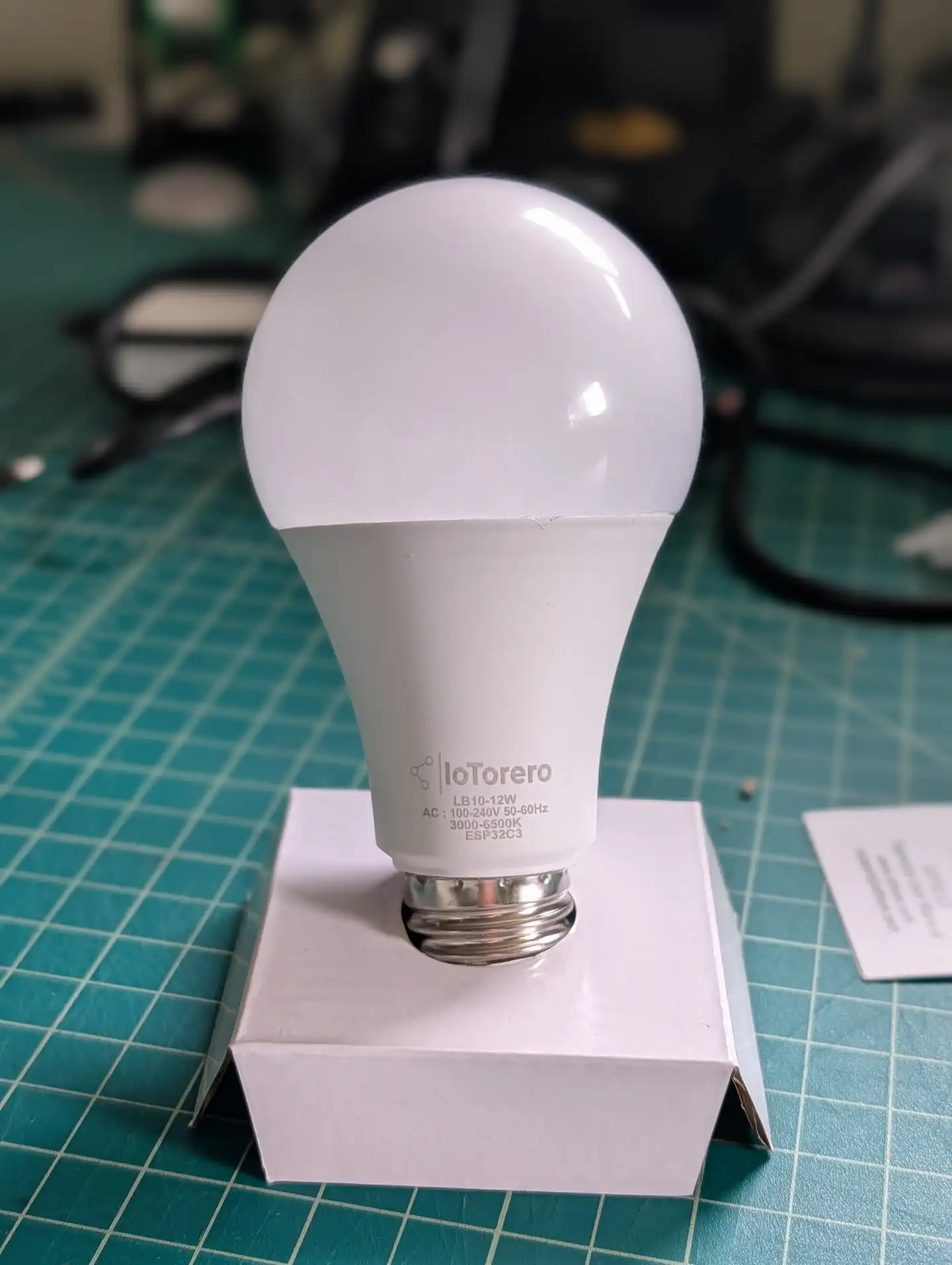
The first thing I wanted to do was open it up and see what I was working with. I was mainly wondering if the pins were exposed so I might be able to attach a microSD card reader. To remove the white plastic bulb on top, I ran a razer blade around the circumference of the bulb in between the base and the bulb. I had to go around twice, the second time angling the knife downward to cut through the sealant inside. Then I was able to just twist and pull the bulb right off. Minimal damage.
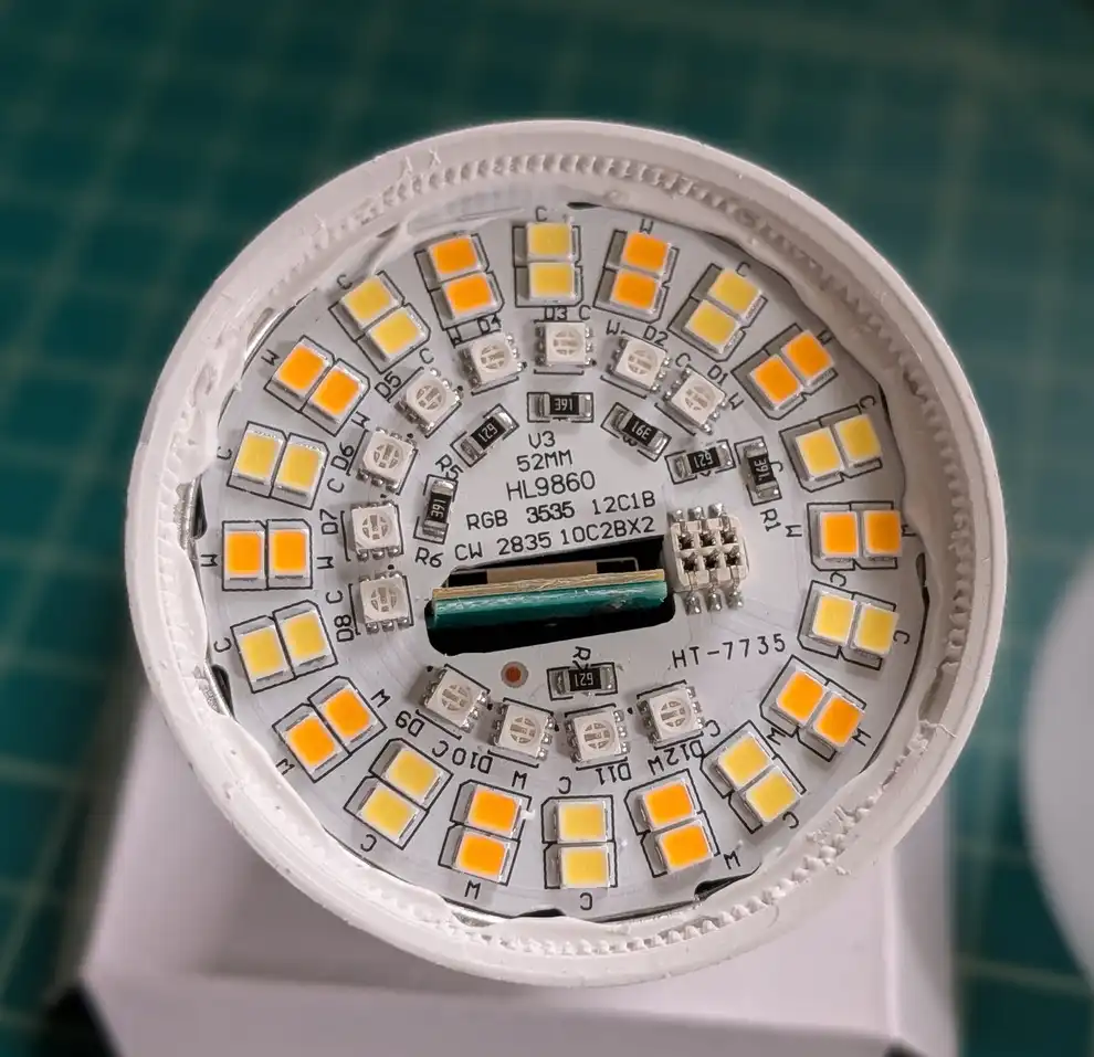
This revealed a round daughter board with all of the LEDs on it. This PCB was attached to another one underneath using six pins. There was also a hole in the middle where the mother board stuck through a bit. This ended up being the antenna for the ESP32. The bulb housing was lined with aluminum and the daughter board was also made of aluminum. So they likely designed it this way to ensure a decent wifi signal.
The daughter board was glued in with more sealant. I used my knife to cut through this and a small, flat screwdriver to carefully pry the daughter board out. I slid it up so it would separate from the mother board.
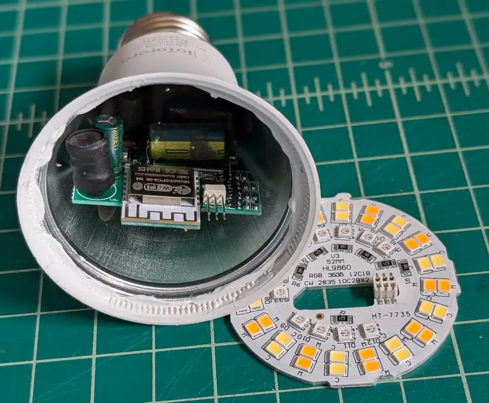
Now I could very clearly see the ESP32C3 inside, as well as some other supporting circuitry. I'm no electronics expert, but I believe most of the components inside are to convert the AC mains power to a cleaner 3.3V DC for the ESP32 as well as whatever voltage was needed to drive the LEDs. I never plugged this device into mains while it was open so I didn't measure the voltage for the LEDs.
One nice thing about this ESP32 was that it seemed to have a bunch of pins exposed. I hoped this might make it possible to solder on a microSD card reader for expanded storage. You can also see some of the pins are labeled at the bottom to let you know which pins are for which colors.
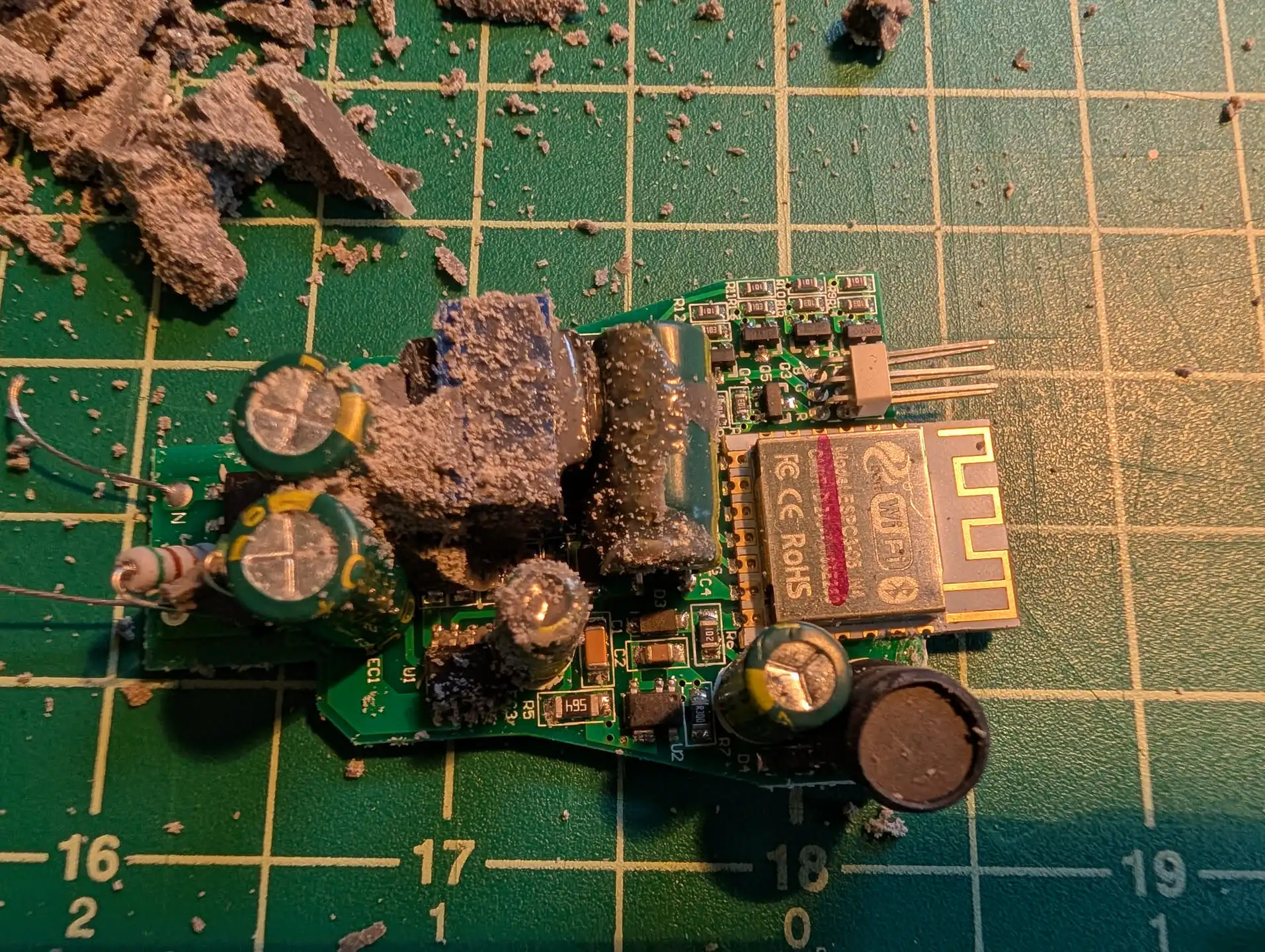
There was really no way to get a soldering iron inside the bulb. The ESP32 only had the antenna portion sticking out above the housing. The only way I was going to solder any wires to those pins was to remove the mother board. Unfortunately this was not a simple task. The mother board was held in place with some kind of rubbery potting compound. There was... a lot of it. I had to dig it out with a knife and screwdriver and then yank the board out.
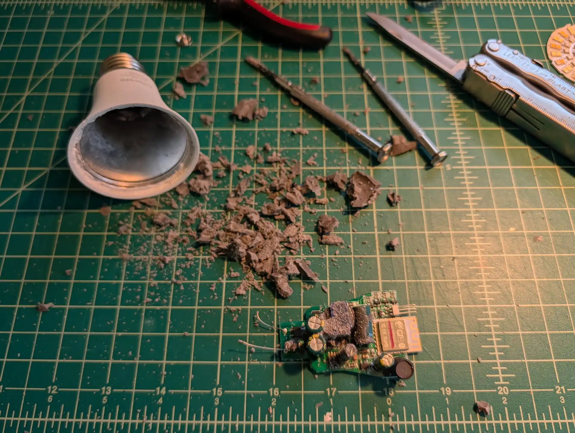
I chipped away a bunch of the compound from the mother board to get a better look at it. It made a mess.
This was a huge pain and not something I would want to be a required step in the process of setting up one of these dead drops. I really wanted this project to be as accessible as possible, requiring minimal tools and hardware skills. Not only that, but there really was no way I was going to get this re-installed properly. And even if I managed to get it back in, I wouldn't trust it to be safe. It could become a fire hazard for all I know.
All that said, this did give me a bit of a development platform to work from. I thought since I had this thing apart anyway, I might as well solder on some wires for serial programming. I had not done this before, so I had to do some reading to figure it out. Basically, I needed to power the chip with 3.3v and ground. Plus I need one wire each for the serial UART TX and RX pins. The first question to answer was which pins were the right pins?
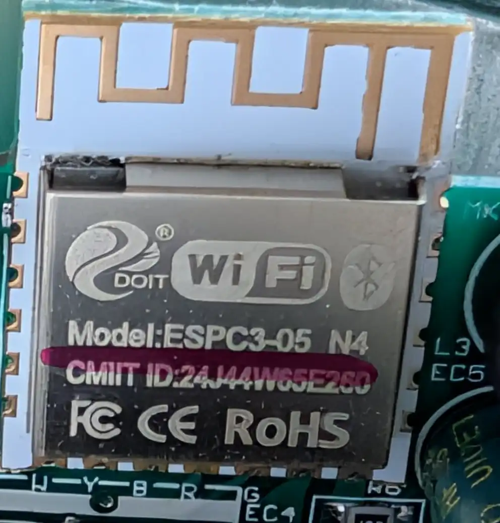
I managed to find this exact module on AliExpress. The listing included an image of the backside of the module, which thankfully had labeled all of the pins.

This helped me figure out the VCC, GND, TX, and RX pins. For GND I ended up just soldering to the metal shielding as it was also grounded and much easier to solder to. I soldered wires to all of the other pins. I had to remove a few capacitors in order to get in there.
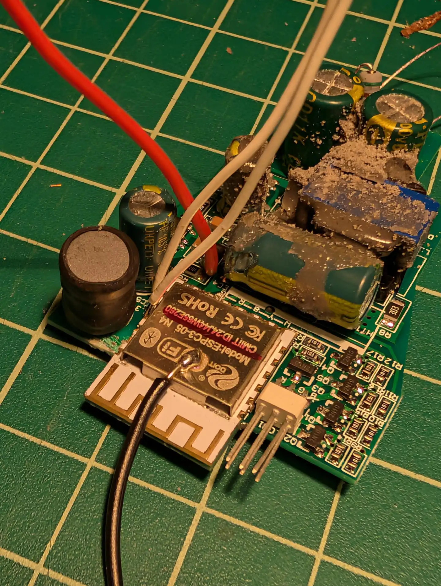
In order to program the device via serial, you have to boot it into a special download mode. This seems to normally involve shorting one of the ESP32 pins to ground while it is powered on. I can't remember how I figured this out, but it ended up bing the IO9 pin in this case. So I soldered another wire there.
I set my bench top power supply for 3.3v and hooked it up to the chip. Applying power to the VCC and GND wires did boot it up and I could see the IoTorerro access point waiting for me to connect and configure the device.
To get it into download mode, I powered the device off. I connected my FTDI device to my laptop's USB port and then to the GND, TX, and RX wires on the mother board. Then I manually shorted the IO9 wire to the shielding to ground it. Then I powered the device on. I could see this time it was only drawing about 0.09 amps, which was much less than before. So something was different.
I thought the first thing I should probably do is try to dump the entire firmware. This would hopefully allow me to flash it back to the device to start it back over from a clean state. I used esptool to do this.
esptool --chip esp32c3 --port /dev/ttyUSB0 --baud 115200 read-flash 0x0 0x4000000 ./tasmota_original_firmware.bin
I could see that it was able to talk to the device and after a few minutes I had a firmware dump! Things were looking good so far.
Early Experiments
Hello World
Early on I went looking at the Tasmota source code to see if I could modify it to act as the Banned Book Library. The firmware was much more complicated than I had anticipated. Not only that but it supported all different architectures and devices. It also had many features I really didn't need. And considering the purpose of my project, I wanted to try and keep the firmware bloat down to make more space for book storage. So I scrapped the idea of modifying Tasmota.
I then discovered that you can program ESP32 devices with Arduino. I had used Arduino a bunch maybe 10-15 years ago, so I had some experience with it. I recalled it being pretty accessible and making it easier to work with embedded systems. But I was definitely rusty and I had never used it to program an ESP32 before.
I setup the Arduino IDE on my laptop and configured it to use my ttyUSB0 serial programmer as well as the proper ESP32C3 chip. I then wrote a very basic hello world program to just send a message over the serial port back to the laptop. This would let me test and see if I could flash the firmware and get the device to do something new.
I used the Arduino IDE's built in upload feature to upload the code to the device. It took care of the complicated stuff and just did it. I checked the serial monitor and found that it was working! I did get serial output from the device. So I was able to write my own firmware to this thing.
Web Server
The next thing I wanted to do was setup an open WiFi access point and Web Server. I believe I started with this tutorial to get an idea of what to do, though I modified it since I wasn't interested in controlling an LED at the time. I later switched to using Async Web Server and used this tutorial to get a handle on things.
MicroSD Card
After getting that working I wanted to try and get a microSD card working. I purchased some breakout boards from Sparkfun.
I went reading the ESP32C3 datasheet to figure out how to wire up the SD card reader. I managed to figure it out eventually. However, instead of soldering to this device, I decided to switch to using an Adafruit ItsyBitsy ESP32 that I had laying around unused from a previous project. The ItsyBitsy was easier to work with because it breaks out all of the pins in such a way that I could solder on header pins. This made it really easy to attach the microSD card reader for prototyping.
Then I followed this other tutorial to figure out how to program the ESP32 to use the device. I did end up getting this to work and even using it to host files for the web server using LittleFS, however the entire idea of adding a microSD did not work out so I won't go into detail on this.
The real problem with the microSD card idea was that soldering wires onto this ESP32C3 in the actual device was a real pain. There was no way to do it without removing the board from the housing which effectively destroys the device as far as I'm concerned. I tried to get creative.
First I looked at repurposing some of the LED controller pins. There were six pins going from the mother board to the daughter board. Five of those were for the various LED colors: warm white, cool white, red, green, and blue. I didn't care about the RGB at all. And I could do away with either the warm or cool white if needed. However this didn't pan out. The way this device is designed, the mother board sends power to the daughter board via one pin. The other five pins route back to transistors on the mother board. The ESP32 turns its GPIO pins high which then triggers the transistors and completes the circuit for each color back to ground. This meant that the GPIO pins could only be used for output at best in this configuration. No input.
I then had a crazy idea to make a "clamp" that could clamp onto the top of the ESP32 and possibly allow some header pins to make contact with the exposd ESP32 pins. I designed a small 3D-printable part that was intended to slip over the ESP32C3 and clamp into place.
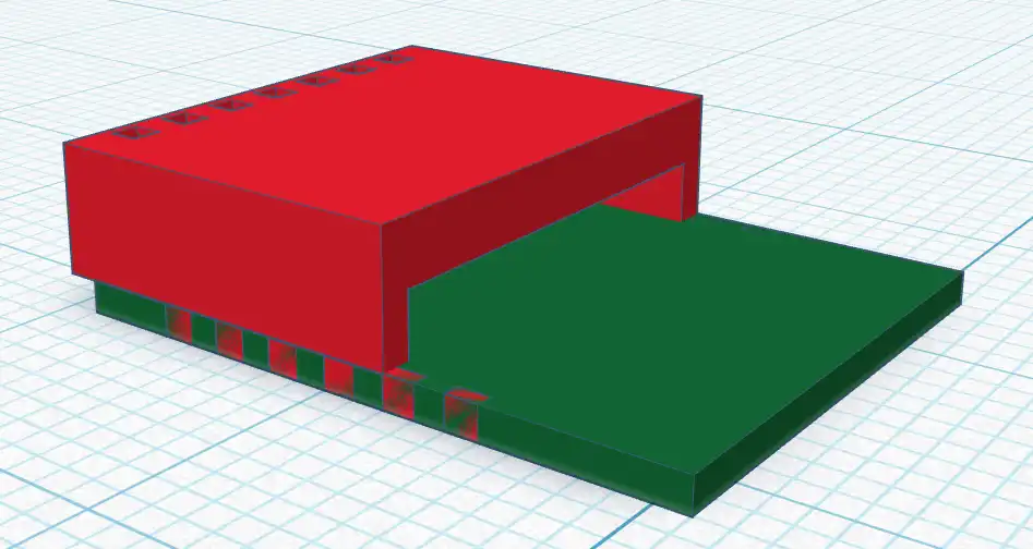
This ended up being way too finicky and unreliable. After several iterations of the design, I abandoned the idea altogether.
Detour
At this point, I decided to try looking at some other bulbs. Maybe there were other devices out there that would lend themselves better to soldering on some extra components? The problem was I didn't want to break the bank buying 20 different LED bulbs just to see if the idea was even feasible. I started by looking into prior research. I found several teardown articles featuring various smart light bulbs, but they all looked very similar to my setup. It did reveal that they don't all use ESP32. At this point I had decided I only wanted to stick with the ESP32 since I had already spent time learning how to program it.
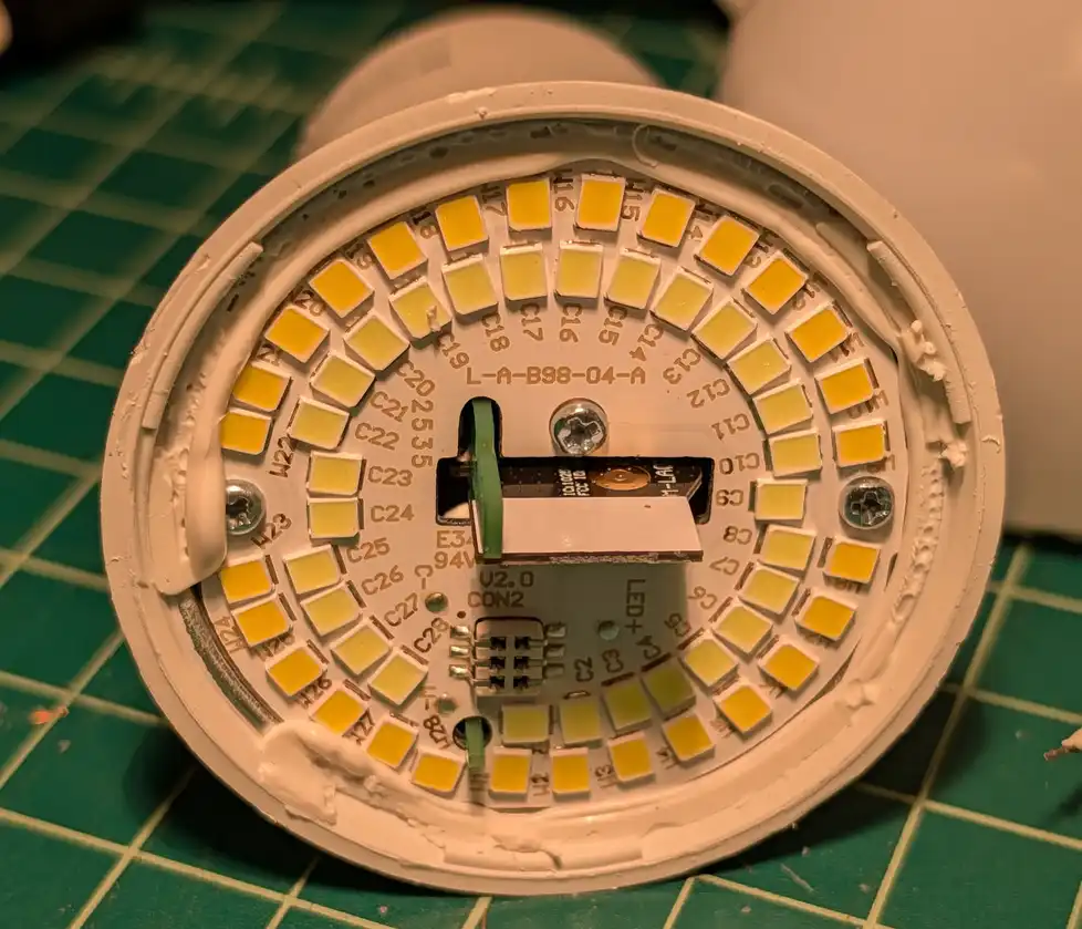
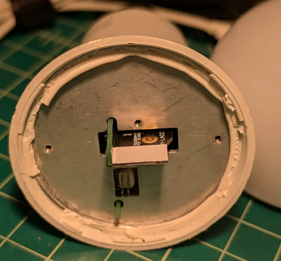
I bought a few bulbs from the local hardware store. One of them had a similar design, but actually had a bit of aluminum protecting the mother board that I couldn't remove safely.
The Philips WiZ looked promising at first. It used an ESP32C3-mini-1 and the entire chip was exposed after removing only the plastic bulb!
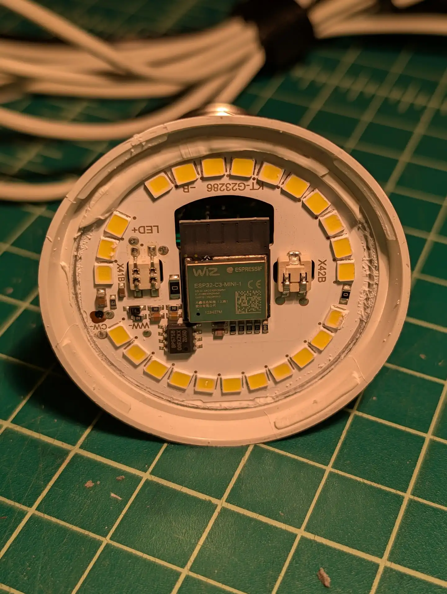
Unfortunately none of the ESP32 pins were accessible on this module. So there was no way to solder wires for anything I needed.
I also tore apart a few standard LED bulbs with no "smart" components. I thought maybe I could just stick my own circuit inside. But this ended up looking more complicated and specialized than just flashing the Tasmota bulb.
There was also an interesting DIY LED smart bulb project I found on Hackaday that intrigued me, but I really preferred the idea of repurposing an off-the-shelf unit.
Ultimately I decided to stick with the Tasmota bulb and to just try to work within my 4MB limitations.
The Storage Problem
To get a handle on the storage situation, we can look at the ESP32 partition table. The table is normally stored at offset 0x8000 in flash, so we can dump this section and then convert the binary to a readable CSV file.
$ esptool -p /dev/ttyUSB0 --baud 115200 read_flash 0x8000 0x1000 part_dump.bin
Warning: Deprecated: Command 'read_flash' is deprecated. Use 'read-flash' instead.
esptool v5.1.0
Connected to ESP32-C3 on /dev/ttyUSB0:
Chip type:          ESP32-C3 (QFN32) (revision v0.4)
Features:           Wi-Fi, BT 5 (LE), Single Core, 160MHz, Embedded Flash 4MB (XMC)
Crystal frequency:  40MHz
MAC:                0c:4e:a0:31:cb:e4

Stub flasher is already running. No upload is necessary.

Configuring flash size...
Read 4096 bytes from 0x00008000 in 0.4 seconds (87.2 kbit/s) to 'part_dump.bin'.

Hard resetting via RTS pin...
I used gen_Esp32part.py to generate a csv file describing the partitions.
$ gen_esp32part.py part_dump.bin
Parsing binary partition input...
Verifying table...

# ESP-IDF Partition Table
# Name, Type, SubType, Offset, Size, Flags
nvs,data,nvs,0x9000,20K,
otadata,data,ota,0xe000,8K,
safeboot,app,factory,0x10000,832K,
app0,app,ota_0,0xe0000,2880K,
spiffs,data,spiffs,0x3b0000,320K,
This revealed five partitions:
- nvs
- otadata
- safeboot
- app0
- spiffs
As I went through this project, I eventually learned that nvs is used for non-volatile storage. This is where the main firmware can store configuration settings like the WiFi network, password, LED color, etc. That way when it reboots, it can remember these settings.
I'm not sure what otadata is used for exactly, other than it has something to do with over the air updates.
The safeboot partition is a second bootable firmware that Tasmota uses to flash the main firmware. It seems that the usual way of dealing with OTA updates is to have two duplicate firmware partitions of the same size. You boot from partition A, and then when you install an update it gets written to partition B. Then you reboot into partition B. If everything looks fine, the firmware can then be flashed to partition A. This way if a firmware update fails on partition B, the device can recover by rebooting into partition A. The downside with this method is that you need to firmware partitions of equal size. This takes up a lot of space.
Tasmota does things a bit differently in the safeboot configuration. Instead of having two duplicate firmware images, there is the main firmware stored in the app0 partition. It then has a second, smaller firmware stored in safeboot. The safeboot firmware can connect to a pre-configured WiFi network and flash the app0 partition and that's about it as far as I can tell. You can't even use the safeboot firmware to configure WiFi. That must be done via the main firmware. Safeboot must read the settings from nvs. The benefit of doing things this way is that the main Tasmota firmware can be larger with more features without taking up double the space for OTA updates. More info on this can be found here.
Finally there is the spiffs partition. spiffs is a file system type but in this case can also represent a more modern LittleFS file system. It's basically a small partition to store files.
With this configuration, the main firmware had close to 3MB of space and the safeboot was close to 1MB. There was just 320K for storage. That might fit one ebook, depending on the length. Not ideal.
It occurred to me that I likely didn't need 2880KB to store my own firmware since mine would be much simpler than Tasmota. I thought I might be able to adjust the partition size from in the firmware itself to shrink the app0 partition and grow the spiffs partition. That would give more space for web files and books.
I eventually did figure out there was a way to do this thanks to this blog post.
Editing the partition table is risky because if it gets corrupted the device may not boot and would only be recoverable via serial programming. This is not ideal, but the whole project is a hack so I guess what the hell?
The partition table is stored at offset 0x8000 in flash memory. So really all we need to do is overwrite the table with whatever we want it to be. We can't just change the partition offsets and sizes though, because there is an MD5 checksum value at the end of the table data. Therefore we would need to update this value as well or the device will not boot. We also can't move the app0 partition while we are booted into that partition or else we will not be able to boot back to this firwmare as it will not be lined up to the start of the partition.
I modified the partition.csv file to look how I wanted the partitions to look and saved it as partitions.csv.new:
# Name,   Type, SubType, Offset,  Size, Flags
nvs,      data, nvs,     0x9000,  0x5000,
otadata,  data, ota,     0xe000,  0x2000,
safeboot, app,  ota_1,   0x10000, 0xD0000,
app0,     app,  ota_0,   0xE0000, 0x120000,
spiffs,   data, spiffs,  0x200000,0x200000,
This would allow for 2MB of data for web server files and books in the SPIFFS partition, which felt like enough to be at least useful. Then I used gen_esp32part.py to generate an actual partition table binary blob from the csv file:
$ gen_esp32part.py partitions.csv.new partitions_new.bin
I used xxd to output the important bits in c array format:
rick@nixlap ~/Projects/BannedBookLibrary/idf/library/main$ xxd -i ../partitions_new.bin |head -n17                                                                                                                                                                                                                                                                                   ✭main
unsigned char ___partitions_new_bin[] = {
  0xaa, 0x50, 0x01, 0x02, 0x00, 0x90, 0x00, 0x00, 0x00, 0x50, 0x00, 0x00,
  0x6e, 0x76, 0x73, 0x00, 0x00, 0x00, 0x00, 0x00, 0x00, 0x00, 0x00, 0x00,
  0x00, 0x00, 0x00, 0x00, 0x00, 0x00, 0x00, 0x00, 0xaa, 0x50, 0x01, 0x00,
  0x00, 0xe0, 0x00, 0x00, 0x00, 0x20, 0x00, 0x00, 0x6f, 0x74, 0x61, 0x64,
  0x61, 0x74, 0x61, 0x00, 0x00, 0x00, 0x00, 0x00, 0x00, 0x00, 0x00, 0x00,
  0x00, 0x00, 0x00, 0x00, 0xaa, 0x50, 0x00, 0x11, 0x00, 0x00, 0x01, 0x00,
  0x00, 0x00, 0x0d, 0x00, 0x73, 0x61, 0x66, 0x65, 0x62, 0x6f, 0x6f, 0x74,
  0x00, 0x00, 0x00, 0x00, 0x00, 0x00, 0x00, 0x00, 0x00, 0x00, 0x00, 0x00,
  0xaa, 0x50, 0x00, 0x10, 0x00, 0x00, 0x0e, 0x00, 0x00, 0x00, 0x12, 0x00,
  0x61, 0x70, 0x70, 0x30, 0x00, 0x00, 0x00, 0x00, 0x00, 0x00, 0x00, 0x00,
  0x00, 0x00, 0x00, 0x00, 0x00, 0x00, 0x00, 0x00, 0xaa, 0x50, 0x01, 0x82,
  0x00, 0x00, 0x20, 0x00, 0x00, 0x00, 0x20, 0x00, 0x73, 0x70, 0x69, 0x66,
  0x66, 0x73, 0x00, 0x00, 0x00, 0x00, 0x00, 0x00, 0x00, 0x00, 0x00, 0x00,
  0x00, 0x00, 0x00, 0x00, 0xeb, 0xeb, 0xff, 0xff, 0xff, 0xff, 0xff, 0xff,
  0xff, 0xff, 0xff, 0xff, 0xff, 0xff, 0xff, 0xff, 0xff, 0xda, 0xa8, 0x74,
  0x2c, 0xcd, 0xc5, 0x28, 0xab, 0xd5, 0x0d, 0xf6, 0x41, 0xd3, 0xa7, 0xdd,
I then dropped it in a partition.h file:
unsigned char partition_table[] = {
  0xaa, 0x50, 0x01, 0x02, 0x00, 0x90, 0x00, 0x00, 0x00, 0x50, 0x00, 0x00,
  0x6e, 0x76, 0x73, 0x00, 0x00, 0x00, 0x00, 0x00, 0x00, 0x00, 0x00, 0x00,
  0x00, 0x00, 0x00, 0x00, 0x00, 0x00, 0x00, 0x00, 0xaa, 0x50, 0x01, 0x00,
  0x00, 0xe0, 0x00, 0x00, 0x00, 0x20, 0x00, 0x00, 0x6f, 0x74, 0x61, 0x64,
  0x61, 0x74, 0x61, 0x00, 0x00, 0x00, 0x00, 0x00, 0x00, 0x00, 0x00, 0x00,
  0x00, 0x00, 0x00, 0x00, 0xaa, 0x50, 0x00, 0x11, 0x00, 0x00, 0x01, 0x00,
  0x00, 0x00, 0x0d, 0x00, 0x73, 0x61, 0x66, 0x65, 0x62, 0x6f, 0x6f, 0x74,
  0x00, 0x00, 0x00, 0x00, 0x00, 0x00, 0x00, 0x00, 0x00, 0x00, 0x00, 0x00,
  0xaa, 0x50, 0x00, 0x10, 0x00, 0x00, 0x0e, 0x00, 0x00, 0x00, 0x12, 0x00,
  0x61, 0x70, 0x70, 0x30, 0x00, 0x00, 0x00, 0x00, 0x00, 0x00, 0x00, 0x00,
  0x00, 0x00, 0x00, 0x00, 0x00, 0x00, 0x00, 0x00, 0xaa, 0x50, 0x01, 0x82,
  0x00, 0x00, 0x20, 0x00, 0x00, 0x00, 0x20, 0x00, 0x73, 0x70, 0x69, 0x66,
  0x66, 0x73, 0x00, 0x00, 0x00, 0x00, 0x00, 0x00, 0x00, 0x00, 0x00, 0x00,
  0x00, 0x00, 0x00, 0x00, 0xeb, 0xeb, 0xff, 0xff, 0xff, 0xff, 0xff, 0xff,
  0xff, 0xff, 0xff, 0xff, 0xff, 0xff, 0xff, 0xff, 0xff, 0xda, 0xa8, 0x74,
  0x2c, 0xcd, 0xc5, 0x28, 0xab, 0xd5, 0x0d, 0xf6, 0x41, 0xd3, 0xa7, 0xdd
};
unsigned int partition_table_len = 192;
I then wrote a function to overwrite the partition table data with this information. The function first checks to see if the partition table MD5 sum already matches the new table. If so, it's already been flashed and doesn't need to be flashed again. If not, then it updates the partition table.
bool edit_partition_table() {

  int result = esp_flash_init(esp_flash_default_chip);
  Serial.printf("esp_flash_init result: 0x%x\n", result);

  uint8_t current_md5[MD5SUM_SIZE];
  memset(current_md5, 0x0, MD5SUM_SIZE);
  result = esp_flash_read(esp_flash_default_chip, current_md5, CONFIG_PARTITION_TABLE_OFFSET + OFFSET_TO_PART_MD5SUM, MD5SUM_SIZE);
  Serial.printf("esp_flash_read result: 0x%x\n", result);

  if (memcmp(partition_new_md5, current_md5, MD5SUM_SIZE) != 0) {
    Serial.printf("Patching partition table...\n");
    result = esp_flash_erase_region(esp_flash_default_chip, CONFIG_PARTITION_TABLE_OFFSET, 0x1000);
    Serial.printf("esp_flash_erase_region result: 0x%x\n", result);

    result = esp_flash_write(esp_flash_default_chip, partition_table, CONFIG_PARTITION_TABLE_OFFSET, partition_table_len);
    Serial.printf("esp_flash_write result: 0x%x\n", result);

    Serial.printf("Erasing NVS partition...\n");
    result = esp_flash_erase_region(esp_flash_default_chip, 0x9000, 0x5000);
    Serial.printf("esp_flash_erase_region result: 0x%x\n", result);

    Serial.printf("Setting default boot partition\n");
    const esp_partition_t * part = esp_partition_find_first(ESP_PARTITION_TYPE_APP, ESP_PARTITION_SUBTYPE_APP_OTA_0, "app0");
    esp_ota_set_boot_partition(part);

    Serial.printf("Restarting...\n");
    ESP.restart();
  } else {
    Serial.printf("Partition table already patched\n");
  }

  return true;
}
This did not work at first. Whenever I tried reading from or writing to the partition table, the API functions would return a success code but wouldn't actually read or write anything. It took some research and testing but eventually I discovered that the ESP32 framework doesn't allow you to access certain sensitive areas of the flash memory for safety reasons. This includes the bootloader and the partition table. When using Arduino IDE to program an ESP32 the framework is preconfigured for you, which makes things easier in many cases. However, one of the configurations has this safety feature enabled. This meant that I wasn't going to be able to edit the partition table using Arduino.
ESP-IDF
After some more research I discovered that the official ESP32 framework is called ESP-IDF. It's more complicated to setup and use but offers greater control over the device and the framework itself.
With more trial and error and head banging I eventually got an ESP-IDF environment setup to see if this would fix my problem. To configure the framework, you can use the command idf.py menuconfig. This opens a menuconfig similar to the Linux kernel. You can use this interactive menu to enable or disable features required for your project. This would also come in handy later when I eventually built my custom safeboot firmware and needed to find a way to shrink it.
In the menuconfig is an option for SPI_FLASH_DANGEROUS_WRITE_ALLOWED. This setting must be set to Allowed. You also must set `SPI_FLASH_DANGEROUS_WRITE_ABORTS to disabled. When you exit the menu, it will reconfigure the IDF with this new setting. Then, you can read and write the the partition table!
However there were more hiccups. Working with the IDF directly meant all of the nice Arduino stuff wasn't going to work. I would have to rewrite my firmware code at a lower level. Or would I? I discovered there's a thing called "Arduino as a Component". When this component is added to the IDF, you can use all of Arduino's niceties but also have greater control over the IDF itself! The best of both worlds! I followed the instructions on that page to get the component setup.
I also then ran into some more problems figuring out how to reinstall the various libraries I was using such as ElegantOTA, Async_TCP, ASyncWebServer, etc. I basically needed to clone the repositories into either my projects components directory or into the Arduino component's libraries directory, depending on the package. I also had to tweak some CMakeLists.txt files. I ended up writing a build.sh script included in the repo that handles all of this for me so I don't have to remember or do it manually.
With allllll of this setup, I was finally able to build the project with idf.py build. Once it compiled I needed to flash it over since I didn't have the Arduino IDE to do it for me. I used esptool again.
esptool -p /dev/ttyUSB0 write-flash 0xe0000 build/library.bin
Setup Page
With my firmware image uploaded, things were starting to come together. The main firmware image includes some of the important web server endpoints but not the actual library code. That is stored in a LittleFS partition and must be flashed separately. To do this, I included ElegantOTA.
When you boot the device without having flashed the filesystem it will present you with a setup page.
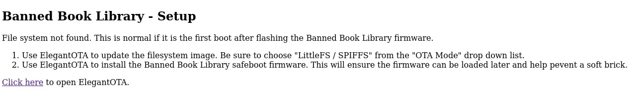
This page walks you through how to use ElegantOTA to flash the filesystem image and also the safeboot firmware.
Safeboot
I wanted to be sure I could perform OTA updates of the main firmware. Originally I thought I could just use the Tasmota safeboot for this. The problem is that Tasmota safeboot uses your WiFi configuration stored in the nvs partition to do updates. This made me realize that the device saves your WiFi SSID and password in plaintext in the nvs partition. This is not good OPSEC! You wouldn't want to leave one of these light bulbs somewhere with your WiFi credentials just sitting there.
To deal with this, I first have my firmware erase the nvs partition. It also erases the SPIFFS partition for good measure. However without the WiFi configuration data stored in NVS, Tasmota safeboot can't connect to any WiFi network. This means you can't connect back to the device to update the primary firmware. I realized I was going to have to make another custom firmware image for the safeboot partition to deal with this problem.
I found this GitHub repo which contained a fairly minimal firmware example that sets up an access point and hosts a minimal web server to perform OTA updates. It doesn't use Arduino, so it should be less bloated and therefore fit in a smaller partition.
I started from this project and then modified bits of it here and there as appropriate for my project. I ended up having to disable some other things in the menuconfig to get the image to fit in the safeboot partition, but it did work!
The safeboot partition is not password-protected, but the admin features of the library are password protected, and you use those features to reboot into safeboot. Good enough.
Web Application
Library
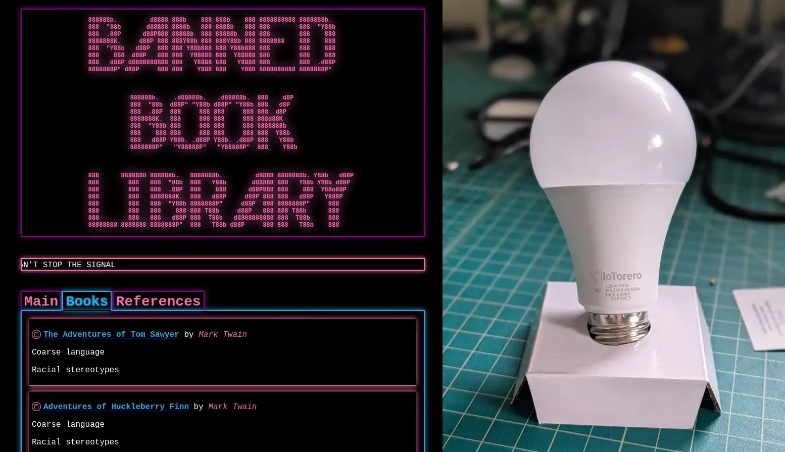
The main experience begins with the index page. This page features an image of a yellow shipping container with a door.
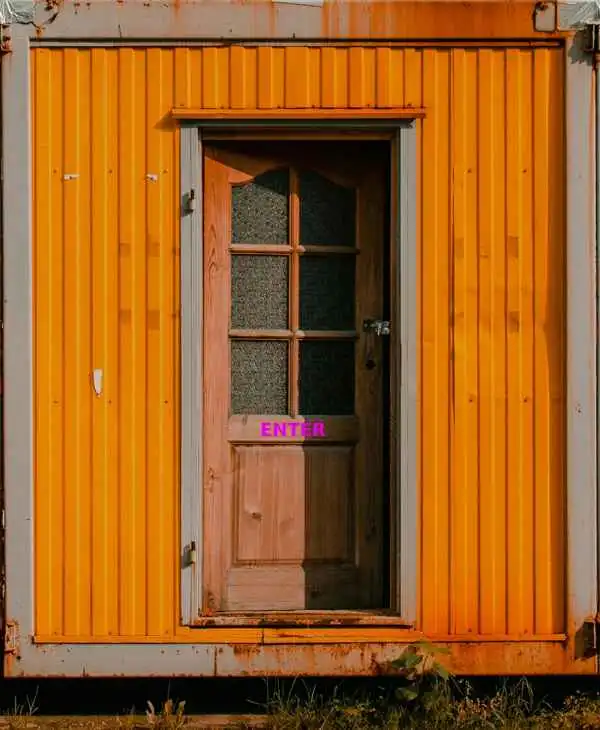
I chose it as a reference to the Ben Brown Library short story mentioned earlier. The image does take up valuable storage space, but I like it so I left it. I included an image "glitch" effect on this page as to make it feel more "hackery". I thought it was cool. I had no idea how to make something like this though. I found the code for it, annoyingly, in a YouTube video. I modified it slightly to suit my needs.
The main library pages were all hand coded by me the old fashioned way... searching for the stuff I wanted to do and then copying, pasting, and modifying to make my own thing. Or else reading about how to do something similar to what I wanted to do and then banging my head against a wall untl I figured it out. I'm not a fan of generative AI. I had to learn more about CSS to make it look pretty. My original plan was to have it be a really basic HTML index page. Just a listing of files. But I eventually decided I wanted it to look cool and be more fun. It also allowed me to learn CSS which I found pretty interesting, actually.
The main site is fairly simple.
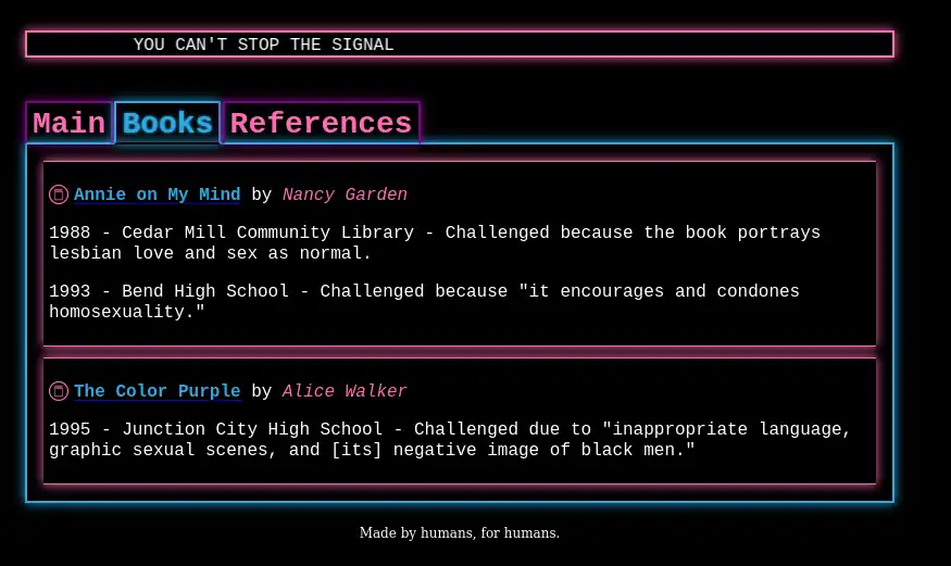
There's a subsection to describe what you are looking at, a section for the books including title, author, and reason it was challenged or banned. Then there is a references section for external links. Though the links won't work while the user is connected because the Banned Book Library's access point doesn't have an Internet connection.
Admin
There is also an administrative panel at /admin.
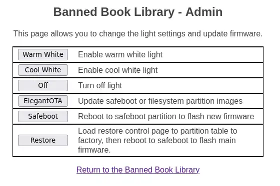
This page is password-protected. It allows you to control the LED color temperature. The idea is that if you drop this somewhere in public, you can try to match whatever color was there before so it is less noticeable that anything changed. This was actually really easy to implement. The company that sells these light bulbs tells you what GPIO pins are used to control each LED color. So you can use AnalogWrite() to set the intensity of each color.
// Turn on cool white light
void handle_cw_on() {
  // Turn everything off
  handle_off();

  // Enable cool white
  analogWrite(CW, BRIGHTNESS);
  prefs.putUChar("color", COOL);
}
I have the library set up to store the color setting in NVS so the next time the bulb is turned on it will return to the same color.
The admin functions also has a button to link to the restore page.
Restore
Restore allows you to somewhat restore the partition table and boot into safeboot.
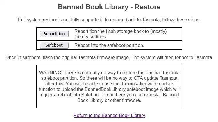
This restore function actually reboots into the custom safeboot partition where you can flash another firmware over top of the Banned Book Library firmware. This could be a new version, or it could be Tasmota, ESPHome, or whatever.
The one problem with restore is I haven't figured out a good way to restore the safeboot partition yet. This means if you do flash Tasmota back, when you click "Firmware Upgrade" in the Tasmota interface it will reboot back into this custom safeboot. It should be usable to update Tasmota but it will not play nice with Tasmota's upgrade experience.
Because of this quirk, the partition restore doesn't completely restore the partition table. It actually leaves safeboot's sub type set to OTA_1 instead of restoring it to Factory. I think Factory partitions are not able to be updated OTA. I left it set to OTA_1 in the hopes that it may somehow allow for an update via a means I haven't figured out yet.
Captive Portal
Having the web server running is well and good, but how would a user know how to reach it? A user who discovers this organically is likely to connect to the open access point and then realize there's no internet connection and give up.
Many access points have captive portal technology. When you connect to the access point your device prompts you to authenticate to the network. It directs you to some web page where you can log in. This is common in places like hotels. I thought I could implement something like this for the banned book library.
I didn't know exactly how this worked, so I looked into it a bit. It seems the old way of doing it was to essentially intercept whatever HTTP request the client made and respond with a redirection to the captive portal. This doesn't work so well nowadays because just about every web site uses HTTPS. The WiFi controller wouldn't be able to intercept and modify the traffic unless the client was configured to trust certificates signed by the controller.
These days it seems there are a few methods. One is to use a DHCP option to specify that a captive portal is in use. Another is that various device types will make specific requests to test for the presence of a captive portal.
As usual, I went looking for example code that already existed to start from. I managed to find some code on GitHub that implements captive portal for the ESP32. It does two things. First it sets up a DNS server that responds to every request with its own IP address. That way no matter what URL is requested, it will direct the user to the EPS32 web server, which is the Banned Book Library. Second, it catches some specific HTTP requests and sends specific redirect responses. It seems the various requests are for Microsoft devices, Android devices, iOS devices, etc. I used a chunk of this code in my own project, which sped things up quite a bit.
// Captive portal things
// https://github.com/LuanTechAutomation/esp-captive-portal/blob/main/src/main.cpp
void config_captive_portal() {
  server.on("/connecttest.txt", [](AsyncWebServerRequest *request) { request->redirect("http://logout.net"); });	// windows 11 captive portal workaround
  server.on("/wpad.dat", [](AsyncWebServerRequest *request) { request->send(404); });								// Honestly don't understand what this is but a 404 stops win 10 keep calling this repeatedly and panicking the esp32 :)

  server.on("/generate_204", [](AsyncWebServerRequest *request) { request->redirect(localIPURL); });		   // android captive portal redirect
  server.on("/redirect", [](AsyncWebServerRequest *request) { request->redirect(localIPURL); });			   // microsoft redirect
  server.on("/hotspot-detect.html", [](AsyncWebServerRequest *request) { request->redirect(localIPURL); });  // apple call home
  server.on("/canonical.html", [](AsyncWebServerRequest *request) { request->redirect(localIPURL); });	   // firefox captive portal call home
  server.on("/success.txt", [](AsyncWebServerRequest *request) { request->send(200); });					   // firefox captive portal call home
  server.on("/ncsi.txt", [](AsyncWebServerRequest *request) { request->redirect(localIPURL); });			   // windows call home

  // catch all
  server.onNotFound([](AsyncWebServerRequest *request) {
      request->redirect(localIPURL);
      Serial.print("onnotfound ");
      Serial.print(request->host());	// This gives some insight into whatever was being requested on the serial monitor
      Serial.print(" ");
      Serial.print(request->url());
      Serial.print(" sent redirect to " + localIPURL + "\n");
  });
}
Final Thoughts
Size Limitation
The device is limited to 4MB of total storage. This is not much space. The few epub books I looked at were around 350KB each. So the light bulb can host a few of these. I had originally imagined a web server with tons of banned books available.
At first this was disappointing but now I actually have grown to like the idea that you are limited on what books you can choose. This means that each dead drop will be representative of the person who created it. They have to pick and choose specific books that are important to them or that they feel are important for others to have access too. I like that idea.
I also like the idea that there could be multiple of these around a given municipality and each one would have different things to find. It could make it more fun to go explore and find these things and see what was left on them for you to discover.
Future Ideas
Color Control
One thing I'd like to do is add sliders to control light color. This would allow for all of the RGB colors as well as finer tuned control over the white color temperature. This way you can more closely match the lights already installed in a given location.
Mesh Networking
I was talking with a friend about this idea and the storage limitation and he thought it would be cool to have these devices form a mesh network. They could use something like distributed hash tables to make all of the books in the mesh available to someone who connects to any device, just as long as the devices are in range of one another. I thought that was a fun idea and may be worth exploring.
Other
Aside from all of that, I have several other fun ideas for repurposing smart devices. These ESP32 chips are so cool! They are dirt cheap and very capable. I will very likely have more ESP32 projects in the future now that I know how to get up and running with them.